Experimentations with QPC - part 2
Quick reminder
If you have reached this post which is the final part of the two-part blog post, kindly visit the preceding blog titled “Experimentations with QPC - Part 1” to understand the necessary know-how required to follow along with the video presentations found in this post.
Presentation Part - 1
Please click on the image below to start the presentation.
In this video presentation, I take the time to show everyone the hardware and software requirements to carry on with the experimentation.
After setting up the environment, the presentation moves ahead with creating the first QM-based model to experiment with direct event posting. In this section of the experimentation, a simple blinky Hierarchical State Machine is created with an ON substate and an OFF substate. They have an external transition linked with the signal BTN_PRESSED. The Button handling ISR routine of the NRF52 MCU is programmed to post an Immutable event stored in the Flash section of the MCU to the event queue of the Blinky active object. This essentially creates an application that toggles the LED when the button is pressed. Since the project is compiled along with the QPSY instrumentation tool, a separate UART program that decodes the QSPY-related messages is run to get more information about the system.
Following the first experimentation, the second one that follows tries the time event feature of the QP framework. Closely replicating the previous QM model, the external transition trigger is now changed to be TIMEOUT signal instead of the BTN_PRESSED signal. The QM model is modified so that during entry into either the ON or OFF states, the time event producer is armed with a predefined set of timeouts which produces the timeout event when the set time expires. The exit actions of both the ON and OFF states are programmed to disarm any existing time events. This essentially creates an application that toggles the LED at a preset amount of timeout. As mentioned earlier, QSPY is still enabled and hence when the external QSPY host software is run on the host computer, meaningful instrumentation data are collected. The ENTRY/EXIT feature of the HSM is a useful technique that provides us with the functionality of constructors/destructors of C++ classes.
Presentation Part - 2
Please click on the image below to start the presentation.
Continuing from the previous video, this presentation starts by experimenting with the publish-subscribe mechanism first. In the QM model, any existing timeout transition triggers and entry/exit actions are deleted. The initial transition is made to subscribe to the button-pressed event. Some storage is allocated in the bsp init function for the QP framework to handle the publish-subscribe mechanism. Finally, the button handler function is designed to publish a static event whenever the function is triggered. This essentially creates an application that toggles the LED when the button is pressed. Running the QSPY tool in parallel yields useful information about the system.
Finally, the presentation moves on to experiment with mutable events. In the QM model, timeout events and button-pressed events are added back. The timeout events are armed and disarmed in the substate entry and exit actions. The blinky constructor now calls memory pool initialization functions to enable the QP framework to deterministically allocate and deallocate storage for the dynamic events. The button handler function increments a counter every time the function is called. This counter is embedded within the dynamic event created in the button handler. This dynamic event is then directly posted to the queue of the blinky active object to be processed. This creates an application where every button press changes the blinky frequency. Running the QSPY tool becomes useful here.
Presentation Part - 3
| Hardware setup | State machine representation |
|---|---|
 | 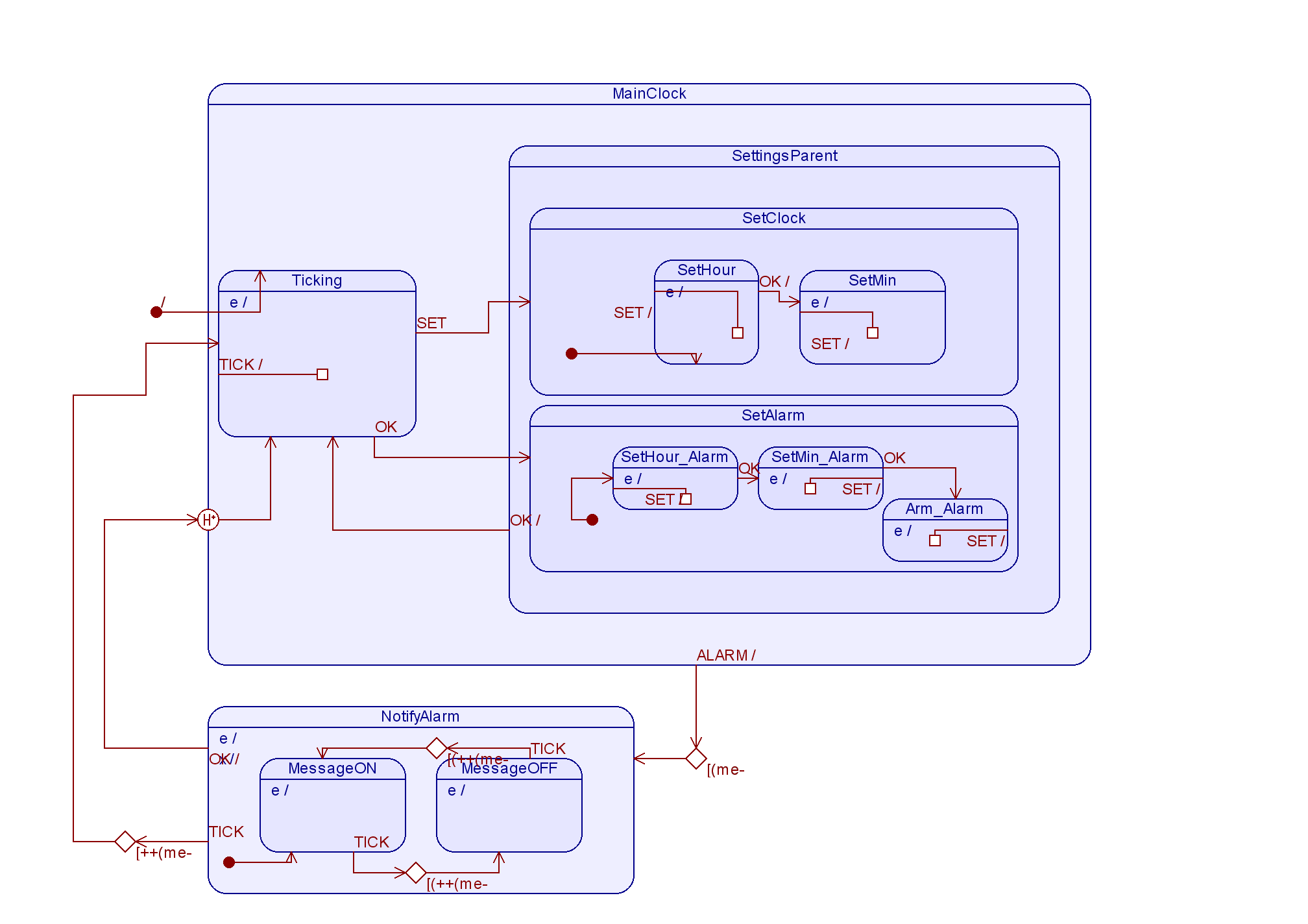 |
When I followed along the Udemy course from Kiran Nayak on the same topic, I experimented with the now-retired QP nano framework. The coursework built a Pomodoro timer using the techniques specified above. Interestingly, the history state technique was used in this experiment. The logic was so: If the Pomodoro timer is already counting from a previous setup, when a set/modification button is pressed, the system goes to the state where one could change the Pomodoro timing setup. If the alarm was supposed to fire, it would do so now, even though the system is in the modification state. When the alarm is cleared, the system setup state is restored to the correct state which was interrupted by the alarm. The history state experimentation was done with the same hardware setup, but the build system was Zephyr-based.
Please click on the image below to start the YouTube presentation: